
Topcon GT-600V Series Robotic Total Stations
Built for building construction, the GT-600V series delivers precise single-operator layout with high-speed ultrasonic motors, LongLink Bluetooth, and IP65 rugged durability. Available in 3-second and 5-second accuracy models.
Choose Your GT-600V
The GT-600V series is purpose-built for building construction layout. Both models share the same rugged platform and high-speed motors. Choose the accuracy level that matches your project requirements.
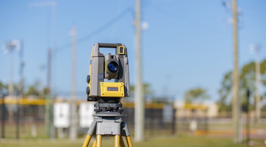
Topcon GT-603V
3″ Angular Accuracy
The go-to choice for most building construction layout work. Three-second angular accuracy provides the precision needed for concrete, mechanical, and structural layout on commercial projects.
| Angular Accuracy (Fine) | 3″ |
| Prism Range | 2,000 m (6,561 ft) |
| Turning Speed | 150°/sec |
| Weight | 5.8 kg (12.8 lb) |
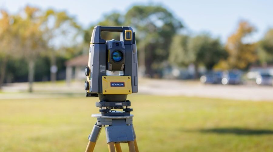
Topcon GT-605V
5″ Angular Accuracy
An economical entry into robotic layout for building construction. Five-second angular accuracy is more than sufficient for general building construction layout tasks where sub-millimeter angular precision is not critical.
| Angular Accuracy (Fine) | 5″ |
| Prism Range | 2,000 m (6,561 ft) |
| Turning Speed | 150°/sec |
| Weight | 5.8 kg (12.8 lb) |
What Is a Robotic Total Station?
The Short Answer
A robotic total station is an electronic surveying instrument that combines precise angle measurement, distance measurement, and motorized target tracking into one tool. Unlike conventional total stations that require two people, a robotic total station allows a single operator to perform layout, as-built documentation, and quality verification from the prism pole using a wireless field controller.
How It Works
The instrument sits on a tripod and uses a laser-based electronic distance meter (EDM) along with a rotary encoder to measure both angles and distances to a reflective prism. Ultrasonic servo motors automatically rotate the instrument to track the prism as the operator moves around the jobsite. The robotic total station delivers real-time ‘left/right’ and ‘forward/back’ guidance to each layout point. When the operator reaches the correct location, the screen turns green for a visual confirmation to mark the point.
Why the GT-600V for Construction
The GT-600V series is specifically optimized for building construction layout. Its compact form factor, high-speed 150-degree-per-second turning motor, and IP65 dust and water resistance make it the ideal tool for the demands of an active construction site. Paired with Topcon Digital Layout software, even operators new to robotic layout can be productive within just a few hours of training.
Key Capabilities
- ✓ Single-person operation with wireless field controller
- ✓ Automatic prism tracking up to 800 m (2,624 ft)
- ✓ LongLink Bluetooth range of 600 m (1,968 ft)
- ✓ Layout 600 to 1,000+ points per day
- ✓ Import DWG, DXF, and PDF design files
- ✓ As-built data collection and QA/QC verification
- ✓ Reflectorless measurement up to 800 m
- ✓ Works indoors and outdoors, no satellites needed
- ✓ BIM workflow integration through MAGNET Enterprise
- ✓ Sub-1/16 inch layout accuracy at typical working ranges
How Contractors Use the GT-600V on the Jobsite
The GT-600V series handles layout across virtually every building construction trade. Here is how the most common trades put it to work every day.
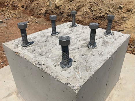
Concrete and Foundations
Layout anchor bolt locations, embed plates, slab edges, and control lines with repeatably accurate results. Eliminate compounding tape measure errors across large pours.
Supported Application
- Point Layout from BIM/CAD
- Control Line Establishment
- Anchor Bolt / Embed Layout
- Penetration and Sleeve Layout
- Equipment Pad Location
- As-Built Verification
- QA/QC Measurement
- Elevation / Level Transfer
Common Tasks
- Anchor bolt layout
- Form lines
- Slab edge layout
- Embed plate placement
- Control line establishment
- Elevation checks
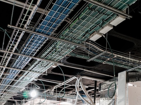
Electrical
Position conduit runs, panel locations, junction boxes, and light fixture mounting points. Accurate first-time placement means fewer field modifications and faster rough-in.
Supported Application
- Point Layout from BIM/CAD
- Control Line Establishment
- Hanger Point Layout
- Underground Piping Layout
- Penetration and Sleeve Layout
- Equipment Pad Location
- As-Built Verification
- QA/QC Measurement
Common Tasks
- Conduit routing layout
- Panel locations
- Junction box placement
- Light fixture centers
- Underground duct bank layout
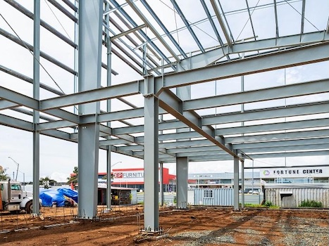
Structural Steel and Masonry
Verify steel column placement, layout bearing wall centerlines, and confirm pier locations. Use as-built measurements to document erected steel positions for the project record.
Supported Application
- Point Layout from BIM/CAD
- Control Line Establishment
- Anchor Bolt / Embed Layout
- As-Built Verification
- QA/QC Measurement
- Elevation / Level Transfer
Common Tasks
- Column centerline verification
- Bearing wall layout
- Pier and footing locations
- Steel erection verification
- Opening locations

Mechanical and HVAC
Lay out hanger points, ductwork centerlines, equipment pads, and piping penetrations from coordinated BIM models. Catch clashes before they become costly in-field problems.
Supported Application
- Point Layout from BIM/CAD
- Control Line Establishment
- Hanger Point Layout
- Penetration and Sleeve Layout
- Equipment Pad Location
- As-Built Verification
- QA/QC Measurement
- Elevation / Level Transfer
Common Tasks
- Hanger point layout
- Equipment pad locations
- Duct centerlines
- Pipe penetrations
- Sleeve locations
- Rooftop unit placement
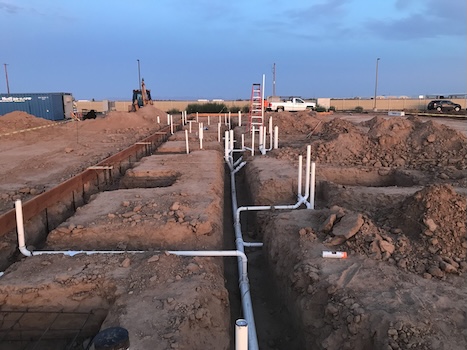
Plumbing
Lay out underground waste and water piping, floor drains, fixture rough-in points, and riser locations with confidence. Accuracy underground prevents expensive rework after the slab is poured.
Supported Application
- Point Layout from BIM/CAD
- Control Line Establishment
- Hanger Point Layout
- Underground Piping Layout
- Penetration and Sleeve Layout
- As-Built Verification
- QA/QC Measurement
- Elevation / Level Transfer
Common Tasks
- Underground piping layout
- Floor drain locations
- Fixture rough-in
- Riser penetrations
- Sanitary and storm routing
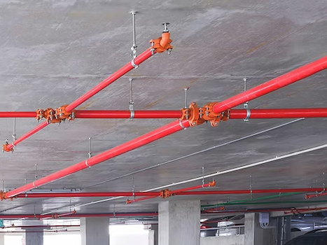
Fire Protection
Layout sprinkler head locations, standpipe centerlines, and fire department connections from coordinated models. Maintain code-required spacing with measurement precision tape measures cannot match.
Supported Application
- Point Layout from BIM/CAD
- Control Line Establishment
- Hanger Point Layout
- Underground Piping Layout
- Penetration and Sleeve Layout
- As-Built Verification
- QA/QC Measurement
Common Tasks
- Sprinkler head layout
- Main and branch line routing
- Standpipe locations
- FDC placement
- Hanger point coordination
Translating Total Station Accuracy to Inches
Positioning accuracy for 3” and 5” class instruments at common distances displayed in construction terms
Fractional inch rounded to nearest common fraction | Formula: offset = distance × tan(arcseconds × π / 648000)
| Distance away from RTS | 3″ Class | 5″ Class | ||
|---|---|---|---|---|
| (ft) | Fraction | Decimal | Fraction | Decimal |
| 50 ft | < 1/16″ | 0.0087″ | < 1/16″ | 0.0145″ |
| 100 ft | < 1/16″ | 0.0175″ | < 1/16″ | 0.0291″ |
| 200 ft | < 1/16″ | 0.0349″ | 1/16″ | 0.0582″ |
| 400 ft | 1/16″ | 0.0698″ | 1/8″ | 0.1164″ |
| 600 ft | 1/8″ | 0.1047″ | 3/16″ | 0.1745″ |
| 800 ft | 1/8″ | 0.1396″ | 1/4″ | 0.2327″ |
| 1000 ft | 3/16″ | 0.1745″ | 5/16″ | 0.2909″ |
* Angular error only. EDM (distance measurement) error is separate: typically ±(1–3 mm + 1–2 ppm). Total positional error includes centering, atmospheric, and target effects.
* Common fractions used: <1/16″, 1/16″, 1/8″, 3/16″, 1/4″, 5/16″, 3/8″, 7/16″, 1/2″, 5/8″, 3/4″, 7/8″, 1″, 1-1/4″, 1-1/2″, 1-3/4″, 2″, 2-1/2″, 3″
GT-600V Series Technical Specifications
At-a-glance performance summary plus complete specifications from the official Topcon GT-600V datasheet.
Training and Resources
Site Precision produces step-by-step video training for Topcon Digital Layout software. Our library is growing every month, and every customer gets access from day one.
Trusted by Contractors Across the Midwest United States
Hear from professionals who have made the switch to robotic layout with Site Precision.
Mario and Brian are extremely knowledgeable about their products. Their customer service is the best of people I deal with. I won’t deal with anyone else when it comes to our laser/total station needs.
More Than Equipment. A Partnership.
When you purchase a robotic total station from Site Precision, you get expert support from day one and every day after.
When You Call, We Answer
Real humans pick up the phone. Our team is available during business hours to troubleshoot field issues, answer software questions, and help your crew stay productive.
In-House Service Department
Calibrations, repairs, and firmware updates handled right here in Grand Rapids. No shipping your instrument across the country and waiting weeks to get it back.
Loaner Units Available
If your instrument needs service, we provide loaner units so your project keeps moving. You should never have to stop work because your equipment is in the shop.
On-Site Training
Every purchase includes startup training at your location. We get your crew comfortable with setup, layout workflows, and software so they are productive from day one.
Remote Support
Need help in the field? Our team can connect remotely to walk through software questions, controller issues, or file management without waiting for a site visit.
Industry-Leading Warranty
Five-year motor warranty and three-year instrument warranty on all GT-600V models. Your investment is protected for years of demanding jobsite use.
See the GT-600V in Action
Schedule a hands-on demo at your jobsite or our Grand Rapids showroom. We will show you exactly how the GT-600V fits into your workflow.